In this post I'll describe my attempt at building a section of a WW2 Japanese carrier deck. Of course, there is a number of commercial products available, but for the most part, they fail to capture the "3D" looks of tie-downs. Moreover, they're not cheap and/or hard to find.
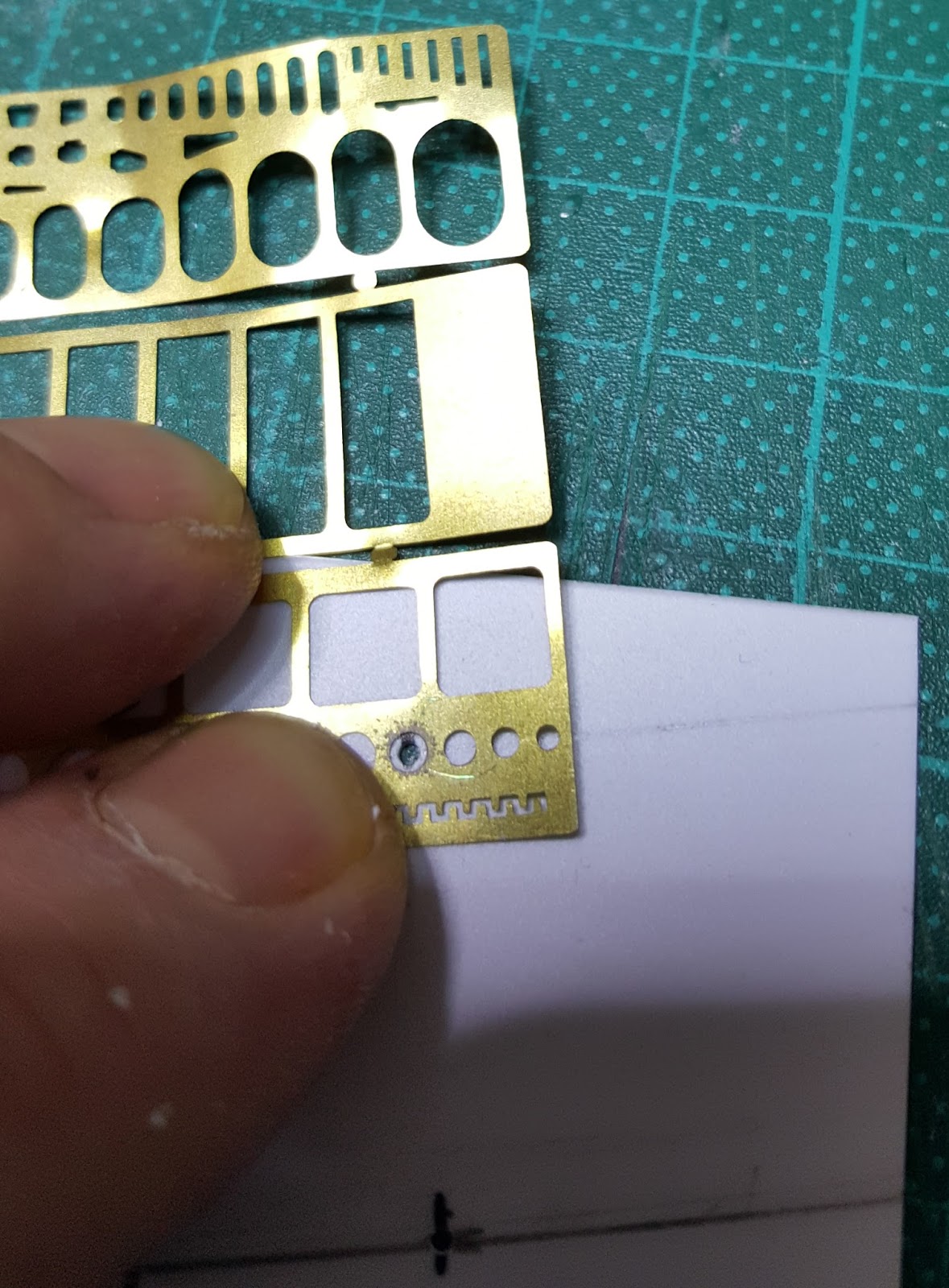
The picture below shows what you will need:

- Sheet of styrene (I used 0.5mm thick, but in hindsight, I would recommend using 1mm for reasons I'll explain later)
- A metal ruler
- A scribing tool ( I use a compass needle in a pin wise)
- A circle scribing template of 2mm diameter
- A 1mm hand drill (the punch and die set you can see in the picture, although it makes cleaner holes, is hard to use in the middle of the sheet...)
- A fine felt-tip pen
- Some reference (in my case an Eduard photo etched sheet depicting a section of the Akagi carrier deck. Sure I could have used that, but, although it is very nicely made, I found the tie downs didn't look like much. Plus it is not very "generous" in its dimensions)
- Some soothing background music
Ok, let's get started. 1st order of business is to cut a rectangular piece of styrene the size you want. Now you're going to mark with the pen parallel lines 2cm apart ( don't get fooled by the picture, I made a mistake and used 2.2 mm...). On these "tie-down lines" trace a dot every 1.4 cm. These will be the centres of the tie-downs.

Now drill a 1mm hole in each dot

Once this is done. it's time to draw the planks. The Eduard sheet shows 2mm wide planks in 1/72, and there are 10 between each "tie-down" line.


Now it's time to carefully scribe the planks. Note that on the "tie-down lines", the line should stop at the edge of each tie-down.

(This is were the soothing music comes into play, you can't afford a mistake here...)
Once done, you will notice that
1) You are 2 hours older
2) Your back is hurting
3) You wonder if you shouldn't have used that photo etched sheet after all
4) and finally the plastic sheet has a distinct curvature due to the heavy scribing. This is why it would have been better to use a thicker sheet. Anyway, nothing that cannot be fixed by a strong adhesive or a dip in boiling water...

It's time to clean the sheet with fine steel wool (which is better than sandpaper as it does not clog the lines as much as sandpaper would), and mark the vertical separations of planks. According to the Eduard sheet, the planks should be 4 cm long in 1/72, and offset by 2cm on each subsequent row (I myself have trouble understanding what I just wrote, so please check the pictures)
Once you're done, it's a good idea to wash the sheet with rubbing alcohol, both to remove dust and erase the pen marks (I have noticed that pen ink has a tendency to "turn" over the years if applied under a coat of paint)

The final step is to flip the sheet over, and glue some stretched sprue across the holes, using liquid cement. These will represent the centre section of the tie-downs.

While the sprue is still soft (due to the action of the liquid cement), you may want to lightly "push" it up so it more or less levels with the rest.

After the glue has set, you can finally glue the sheet to your base. Et VOILA!

Here is what it looks like after a first coat of Tamiya dark yellow.

I'll show you the final version in a future post, but right now I feel a strong urge to return to important matters. Namely continue playing Uncharted IV....
Happy Modelling!
Treflon
No comments:
Post a Comment